RPM Sensors
RPM sensors typically use different types of wiring depending on their technology and application. However, most RPM sensors, such as Hall effect, optical, or inductive sensors, generally have the following connection:
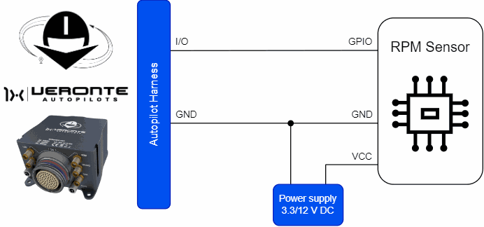
RPM sensor must be connected to one of the available I/O pins of Autopilot 1x.
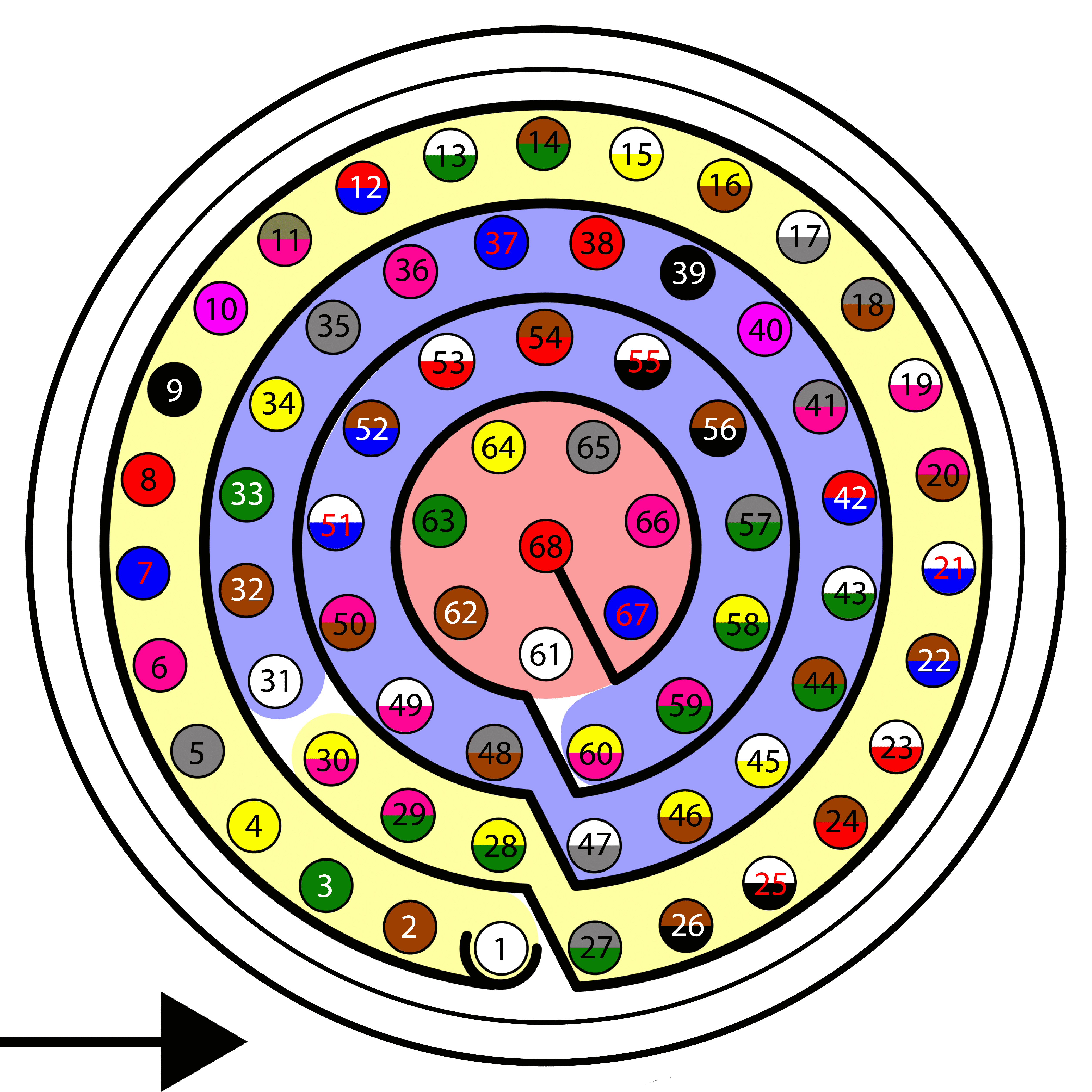
| Autopilot 1x Harness | ||
|---|---|---|
| PIN | Signal | Color Code |
| 1 | I/O0 | White |
| 2 | I/O1 | Brown |
| 3 | I/O2 | Green |
| 4 | I/O3 | Yellow |
| 5 | I/O4 | Gray |
| 6 | I/O5 | Pink |
| 7 | I/O6 | Blue |
| 8 | I/O7 | Red |
| 9 | GND | Black |
| 10 | I/O8 | Violet |
| 11 | I/O9 | Gray-Pink |
| 12 | I/O10 | Red-Blue |
| 13 | I/O11 | White-Green |
| 14 | I/O12 | Brown-Green |
| 15 | I/O13 | White-Yellow |
| 16 | I/O14 | Yellow-Brown |
| 17 | I/O15 | White-Gray |
| 55 | EQEP_A | White-Black |
| 56 | EQEP_B | Brown-Black |
| 57 | EQEP_S | Gray-Green |
| 58 | EQEP_I | Yellow-Green |
| 59 | GND | Pink-Green |
Once the hardware installation is complete, to properly integrate the device with Autopilot 1x follow the steps detailed in the RPM Sensors - Integration examples section of the 1x PDI Builder user manual.
© 2025 Embention. All rights reserved.